Every company has a responsibility to ensure a safe working environment for their employees, your reliability program should be adding to this, and thermal imaging has a very important role to play.
Have you considered how your role as a Reliability Engineer, and the decisions you make, affects the drive to a safer working environment?
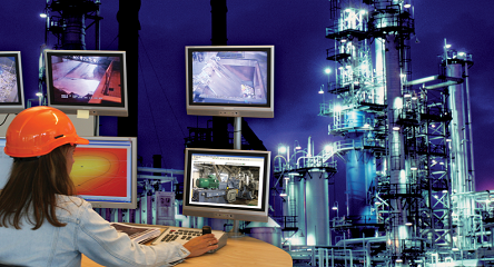
As Reliability Engineers we are in a unique position that allows us to influence the culture of a plant. We do so by education, demonstration and documentation of efforts, to improve the operation of the facility.
One of the many technologies we have at our disposal is thermal imaging. This is not new technology, but very few people are able to look past the very obvious application, electrical hot spot chasing.
Yes, believe it or not, many users and companies see the identification of “hot spots” in electrical systems as the primary use for thermal imagers. A very sad situation indeed.
To really understand what thermal imaging can offer, you need to be willing to “play with your toys”. You need to set aside what you thought you knew, get out into your plant, and play. This is how we learn.
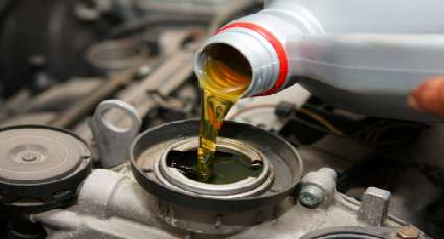
Many industries rely on heat and other forms of energy to transform their ingredients into a product. Many times, generation of heat is the result of a process, and needs to be released in some way.
Thermal imaging is the perfect tool to observe many of the influences of this heat. We may observe the level of liquid in a vessel, the degradation of refractory over time, the release of energy in heat exchangers and so forth.
Reliability Engineers should also be aware of the safety requirements associated with their plant and industry. There are many, such as oil and gas, chemical and the energy sector that follow strict regulatory guidance associated with ATEX/HAZLOC zones.
These ATEX/HAZLOC zones are defined as such due to the volatile liquids, vapours or dusts within the manufacturing cycle which could also potentially be released to atmosphere.
In many cases there are casing temperature limits set for items in these areas, these will vary according to the product produced, but will always be specified in the plant design documentation and must be displayed on the component nameplate, as specified in the manufacturing standards for the equipment.
Other sources of ignition do exist and may be summarised as follows:
- Heat energy e.g. heating installations.
- Electrical energy e.g. earth fault, conductor fault, loose contact, induction heating and resistive heating.
- Mechanical energy e.g. friction, impact and grinding.
- Chemical energy e.g. self-heating, impact and heat-sensitive materials and runaway exothermic reactions.
So far, we have considered the impact of these energy releases on the product, but what about the impact on people?
Humans are very curious and as such investigate the world using the sense of sight, hearing, smell and touch. Touch is often used by plant personnel to define if an asset is “warm” or not, even though this may not be the wisest thing to do. But none the less they do so.
The result is that employers are required to ensure that surfaces accessible to employees, as noted in the UK for example in a BS EN standard, do not exceed various levels. There may be exceptions, as defined in the standards, but in all cases, employers want to avoid any harm being done to their employees.
Harm cannot only be ascribed to the physical nature of burning or scalding, but also to the psychological effects injuries have on people. Everyone reacts differently to traumatic incidents.
As reliability engineers we should strive to apply the techniques and technologies available to us, in a manner that delivers value in safety for both the plant and our people.
I am not going to delve into too much detail now, but rather leave you with a few thermal images demonstrating what can be achieved if we paid a bit more attention to the thermal world around us.
Friction
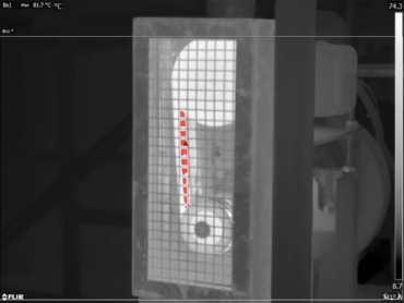
V-Belts overheating
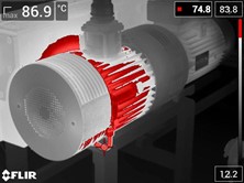
Seal overheating
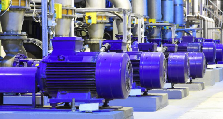
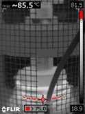
Hot component casings
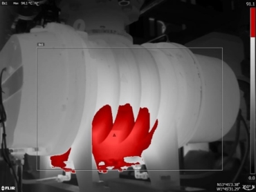
Unexpectedly hot assets and normally cold objects
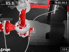
Pump and pipework where thought to be at ambient tempature
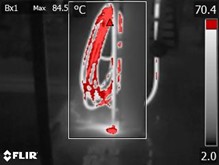
Hose pipe hung in the plant, but venting steam. There were no warnings about the steam.