Articles  

Motion Magnification Real-Life ODS

Michael Howard, DSc | CEO, ERBESSD-INSTRUMENTS

What is Real Life ODS

Real life ODS is a new way to visualize the vibration of a machine in the same way you used to do it using conventional ODS. Thanks to the technology developed by Erbessd Instruments you can collect data with your accelerometers and after that, just take a picture and you’re ready to complete a motion magnification analysis.

ODS analysis

Operating Deflection Shape (ODS) analysis is a widely used method to analyze vibrations on machinery systems and even civil engineering structures under external unknown forces. These forces may include engine speed, unbalance, misalignment, load, temperature, pressure, etc.

Traditionally, this type of analysis requires to create a 3D CAD model and obtain vibration data measured in the field with accelerometers to obtain a 3D animation that exemplifies the vibration effects on the machine or structure. However, the creation of such accurate 3D motion magnification studies is very time consuming because 3D models are not typically readily available and must be developed Furthermore typical vibration analyst’s and engineers do not necessarily have the skills required to create the aforementioned 3D model. Traditional ODS analysis has proven to be a valuable tool for troubleshooting of mechanical and hydraulic problems and a traditional 3D ODS module is already included in our DigivibeMX® Software.

ODS 3D Simulation
Dragon Vision Results

Real-Life ODS Technique

Real Life ODS allows us to save precious time by removing the need of a 3D model, and achieve the visualized motion magnification with a single still image of the subject.

First, the user loads the signals, photos of the equipment and selects the measured points. Next,  DragonVision applies bandpass filters to the spectrum (FFT) to eliminate noise. Finally, the program creates 2D amplified vibration animations that contain projected 3D data from the combination of time series and frequency data by applying the Real Life ODS method to the image.

The resulting map shows small, and high frequency displacements and deflections that were not visible to the human eye.

How to do Real-Life ODS

Data collection for Real Life ODS with accelerometers is identical to the traditional vibration measurements. The advantage of this technique is that it allows you to achieve motion magnification from a wide variety of sensors and frequencies, ranging from very low frequencies in the case of civil engineering and ground vibration data, to high frequencies, e.g. High-speed turbines. The motion magnification data accuracy, amplitude, resolution and sensitivity depend solely on the selected accelerometer according to your specific needs. This ensures a fully calibrated signal and model and thus far out-performs typical video deflection analysis technology as developed by ERBESSD INSTRUMENTS and others that use similar video vibration data analysis methods.

Choosing the right accelerometer for Real-Life ODS

For any vibration analysis with accelerometers, it is important to keep in mind that the maximum amplitude and frequency range of the measured vibration determines the sensor range needs. When measuring vibration that is out of the specified range for the sensor, the signal will be distorted or saturated due to non-linear electrical response.

Another important parameter when choosing an accelerometer is its sensitivity. This parameter usually is expressed in mV/g (millivolts per gravity units or millivolts per 9.81 m/s2). For example, if an accelerometer has a sensitivity of 100 mV/g and the measured signal is 10 g, it is expected to obtain 1000 mV electrical output reading. Typically, this value is constant for a given frequency range of each sensor. As a rule of thumb, low sensitivity accelerometers have a higher amplitude range and high sensitivity accelerometers have low amplitude range.

WiSER 3x

Wireless Triaxial Accelerometer
  • Triaxial Accelerometer
  • Full bandwidth 15kHz
  • Sensitivity of 100 mV/g
  • Long distance range up to 20m
  • Stainless steel housing
  • Operation temperature up to 185ºF (80ºC)
  • Ideal for Real Life ODS & Route Based Data Collection

EI-WiSER

Wireless Accelerometer
  • Monoaxial Accelerometer
  • Full bandwith 15kHz
  • Ultra low-noise accelerometer
  • Long distance range up to 15m
  • IP67 Grade
  • Li-ion Rechargeable Battery
  • Ideal for Real Life ODS & Route Based Data Collection

GX400

4 Channel Interface
DigivibeMX Electronics
  • 4 Channel Wired Interface
  • 2 ICP monoaxial Accelerometers (100 mV/g)
  • Frequency range up to 15kHz
  • Up to 4 Simultaneous Channels of Data Collection
  • No Calibration of GX400 Required as NIST Traceable Accelerometers are Calibrated
  • Ideal for Real Life ODS & Route Based Data Collection
Processing Vibration Data to complete a Real-Life Motion Magnification ODS

For better motion magnification results it is recommended to use a single axis accelerometer (as the reference sensor) and one “mobile” triaxial accelerometer for measuring different points of interest.  The following is a summary of the workflow in our DragonVision Motion Magnification Software.

Collecting data for Vibration Visualization using DragonVision

  • Place the reference accelerometer in a low vibration region of your system (such as the base) and record.
  • The triaxial accelerometer has to be placed in the regions of interest, e.g. bearing locations, gearboxes, spinning blades, etc. With Real Life ODS you can measure a single point, however when creating the Real Life ODS animation it will not be representative of the actual scenario with just one point of data.
  • For more fidelity in the Real Life ODS animation, it is recommended to measure at least one point per bearing location (in the case of rotating equipment) and map the regions that may have greater vibration amplitude in your system. Using more triaxial measurement points will result in a higher fidelity and more accurante Motion Magnification animation.
  • When measuring different locations, try to keep the same axis orientation in the triaxial accelerometer. If this is not possible, take note on the axis orientation for each measured point. This information will be useful when transferring the data to DragonVision.
Compressor without phantom
  • Depending on the range of frequency measurement desired, each measurement has to contain at least two full cycles (e.g. if the lowest expected frequency is 1Hz, your measurement should record a minimum of 2 seconds)

Once in DragonVision Real-Life ODS Software

  • Take at least one still photo of the system that is being analyzed, where most of the measured points are shown. We recommend an isometric view of the whole system to visualize the 3D components of acceleration. However, if more views are required (e.g. top view, side view, etc.) you can capture more images to produce animations of multiple views. There is no minimum nor maximum requirement for the camera resolution. However, we recommend at least 2 MP image resolution (equivalent to Full HD resolution) for the best animation results. DragonVision is compatible with JPG, PNG, BMP and TIFF formats.
  • In DragonVision, load one image and load the signals recorded in the field.
  • The single axis accelerometer is now used as a reference to synchronize all the measurements done with the triaxial sensor, the resulting signals should all be in phase.
  • In the loaded image, draw the H, V and A axes according to the accelerometer measurements orientation. This step is important to calibrate the angle of the photo with the accelerometer components and obtain the proper vibration projections within the model.
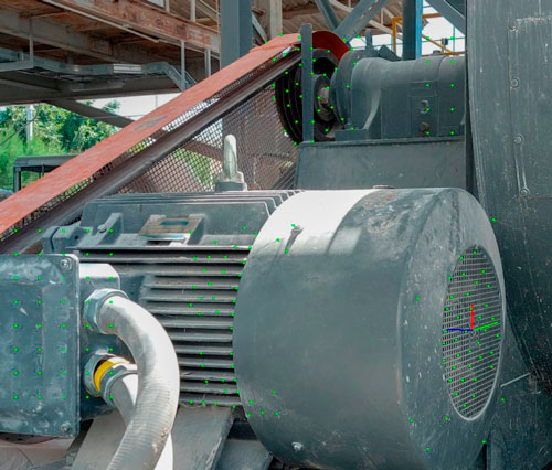
  • For each measured point, select the corresponding region in the photo to generate its warp points and assign the corresponding signal/spectrum (automatic point detections or grid points). The deformed animation will contain the values from the spectrum in the points generated. For the rest of the deformed image, DragonVision will automatically interpolate amplitude values. Automatic point detection is recommended when generating a quick preview of deformation without masks. Grid points are recommended when a polygonal mask is used to draw the contours of the region to be deformed.

null

Dragon Vision
No more tons of hours spend building 3D Models!
Create Real Life ODS with a single picture.
Take a photo and load your vibration Data.

Learn more!

Processing Motion Magnification using DragonVision

  • Select the desired frequency in the vibration spectrum that is going to be visualized with Real Life ODS. In this graph you will be able to clearly see amplitude peaks and visualize as many of them as you want.
  • Optionally you can draw inclusion/exclusion masks in the image to isolate the deformation from other equipment or background that may be in the image field of view.
  • Tune the amplification factor so that motion can be clearly visualized in the animation.
  • Tune the filter factor to smoothen or sharpen the motion at the edges of the deformed/warped region.
  • Define the number of frames to be created for the animation. Higher number of frames will show a smoother and slower animation. However, if the number of frames is very high, computing time and video file size will grow considerably. We recommend the number of frames to be between 20 and 30 (default is 20).
Points Dragon Vision
  • Optionally you can show the generated points in the animation by activating the corresponding checkbox
  • Preview the Real Life ODS results by clicking in “Warp Image”. (Exit preview by pressing any key)
  • Tweak amplification, Filters, and number of frames until you are satisfied with the results.
  • Save the Real Life ODS result as an mp4/GIF video file once you finished.
Pump after Balancing

Machine before and after balancing process.

Why use accelerometers in Real Life ODS?

Vibration Analyzers most commonly use Accelerometers due to their excellent frequency and amplitude range as well as the low floor noise. In return, they convert acceleration into other parameters like velocity and displacements which are more frequently used in vibration analysis.

For example, with the help of our wireless  triaxial accelerometer Wiser 3X, you can get 3D vibration spectra up to 15,000 Hz with a sensitivity of 100 mV/g with remarkably high precision due to the great spatial and temporal resolution provided by field-proven accelerometers. With this, you will be able to detect bearing issues, gearbox problems and much more.

Additionally, DragonVision is compatible with 3rd party accelerometers so you can start generating Real Life ODS visualizations right away and the accuracy and resolution is only limited by the type of accelerometer you use.

Motion Amplification/Video Vibration Vs’ Real Life ODS

In contrast, Video Vibration Software uses cameras to record the vibration in 2D and are limited by the recording resolution and framerate. For instance, using a common cellphone camera allows you to detect frequencies only up to 120 Hz (slow motion mode with iPhone). This video vibration technology becomes inherintly more expensive as motion based video vibration analysis such as those developed by others in the market is cost prohibitive and requires a dedicated PC for post processing.

In the case of  cost prohibitive, specialized high-speed cameras you could get vibration spectra only up to 6,250 Hz (Phantom V2640 12,500 fps @ Full HD resolution). While this is useful to have a big picture of the behavior for a complete area, it lacks accuracy when analyzing more in-depth problems in your machine components. Moreover, when measuring with video vibration analysis, one must be very careful about the position and calibration of the camera to obtain accurate 2D data. (It is important to mention that is nearly impossible for actual single camera motion amplification techniques to accurately measure 3D displacement or 3D acceleration and they just provide data of a 2D projection, nor is the calibration NIST traceable). 

Most real problems require 3D information or high sampling frequencies to get a proper diagnostic, and this is where video based Motion Amplification fails.

Subscribe
Notify of
guest

This site uses Akismet to reduce spam. Learn how your comment data is processed.

0 Comments
Inline Feedbacks
View all comments

About the Author

Michael Howard, DSc CEO, ERBESSD-INSTRUMENTS

M. David Howard  is an American entrepreneur, a veteran of the United States Air Force, and respected leader in the predictive maintenance industry. Michael is an avid CrossFit® athlete, CrossFit® CF-L1 Trainer and passionate advocate of revolutionary concepts in the wireless instrumentation and the IIoT communities for the maintenance & reliability industries.

Dr. Howard is a native of South Glens Falls, New York and a graduate of Excelsior College, Capella University, & Charter University with degrees in Electro-Mechanical Engineering, Leadership, & Organizational Management, & Engineering Management. David is a Certified Reliability Engineer, Six-Sigma Black Belt & Certified Maintenance & Reliability Professional. He is the CEO of Erbessd Instruments and is responsible for Strategic Direction, Distribution, Sales, Marketing and Operations worldwide.