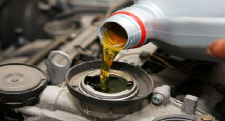
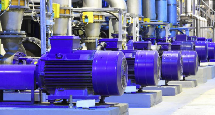
One electrical energy storage system that utilizes common components that you would see in an industrial or manufacturing facility is the flywheel. A flywheel is a motor/generator and variable frequency drive that turns a mass connected to the motor shaft up to a design speed and maintains the speed until it needs to bleed the kinetic energy back in the the electrical system by turning the drive into reverse and drawing power from the system. The efficiency of the system depends on the friction present in the system such as with air or bearings.
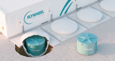
Figure 1: Flywheel storage system example
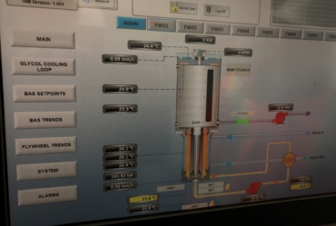
Figure 2: Flywheel control system (0.5 MW cell)
With all of the different designs of flywheels, the a vacuum is drawn to reduce air friction and magnetic bearings are often used to reduce mechanical friction. The vacuum must be low enough to fall below Paschen’s Law values, such as 0.8 mmHg when sealed insulation systems are present (reference: “Evaluation of Offline Partial Discharge in Vacuum Environments,” 2019 Electrical Insulation Conference, Institute of Electrical and Electronics Engineers, Penrose and Dreisilker). The purpose is to be able to store as much energy as possible without these losses and without the destruction of the components. The primary issue being the electrical insulation. As a result, some of the designs seal the motor/generator with a ‘can’ allowing the windings to operate in vacuum. However, this causes an increased air gap and other losses reducing the efficiency of the system.
The system shown in Figure 2 was the result of a joint project between a flywheel company based out of Mississauga, Ontario, and Dreisilker Electric Motors Glen Ellyn, Illinois, based on “Evaluation of Vacuum Encapsulation Systems for Integral Motors,” (2011 Electrical Insulation Conference, IEEE, Penrose and Wittmuss). As shown in Figure 3, destructive discharges (glow discharge) occur in the insulation systems and to ground in low atmosphere, meaning the windings would be vulnerable should there be a atmosphere leak allowing the equipment to operate at a reduced effectiveness while repairs are being scheduled.
Figure 3: Unsealed winding at 2mmHg resulting in glow discharges
The application of the sealed windings using commercially available encapsulation systems and a proprietary process which eliminated the exposure should a leak occur. During testing of the seal system, shown in Figure 4, the fast rise time voltage is brought up well above expected voltage resulting in arcing between electrical contacts outside the machine but not in the stator winding.
Figure 4: Sealed winding lack of glow discharge at higher voltages and frequencies. Glow discharge between connections.
In the Federal government and commercial designs, there are a variety of designs including cylinders and solid mass systems. The mechanical components have lower failure rates with the effectiveness and reliability of magnetic and related guide bearings. The upper speed limit and resulting Watt-hour capability is based on the mechanical limits of the flywheel and shaft.
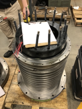
Figure 5: Stator and water Cooling Inner Jacket for 500 kW flywheel motor-generator
Overall, when properly applied, flywheel technologies can be repaired through commercial repair companies with some specialized training. Upon retirement, the components can be recycled in the same way as industrial and commercial motors and drives. Utility-scale flywheel technology is presently limited to about 58 MW in the USA and is primarily used for load leveling and power management.