In Part 1 of the series the theoretical aspects of AC motor faults patterns were presented. Moreover the most common frequencies produced by electrical motors were discussed to ensure the analysts understand which are these and how are calculated.
In Part 2 the practical example will be analyzed.
Let’s look the background and calculate the most common frequencies produced by motor that potentially will be required for further analysis.
- Motor type: AC
- Power: 355 kW
- Running speed: 1485 rpm
- Running speed rounded up to the nearest hundred: 1485 rpm >> 1500 rpm
- Electrical line frequency (FL): 50 Hz = 3000 cpm
- of poles (P) = 2x FL / NS = 2x 3000 cpm / 1500 cpm = 4
- Slip frequency (FS) = 1500 cpm – 1485 cpm = 15 cpm
- Pole pass frequency (FP or PPF) = 15 cpm x 4 = 60 cpm
- Twice the line frequency (2x FL): 2x 50 Hz = 100 Hz (6000 cpm)
Required information, while analysis done will be also rotor bar pass frequency (FB or RBPF). For this, however, it will be sometimes not that easy to have this information, especially it is not the rule to have this data in technical documentation.
Nevertheless, even if you do not know the number of rotor bars, but you see a high frequency peak, usually in a range between 35 to 96 (most common number of rotor bars) multiplied by the running speed then you can be somehow confident that the rotor bars fault condition exists. Moreover rotor problems are indicated by sidebands at twice the line frequency around the rotor bar pass frequency and / or its harmonics what clearly confirm as above.
Having all the most common frequencies produced by electrical motor collected time to see the practical case study.
Let’s look the spectra.
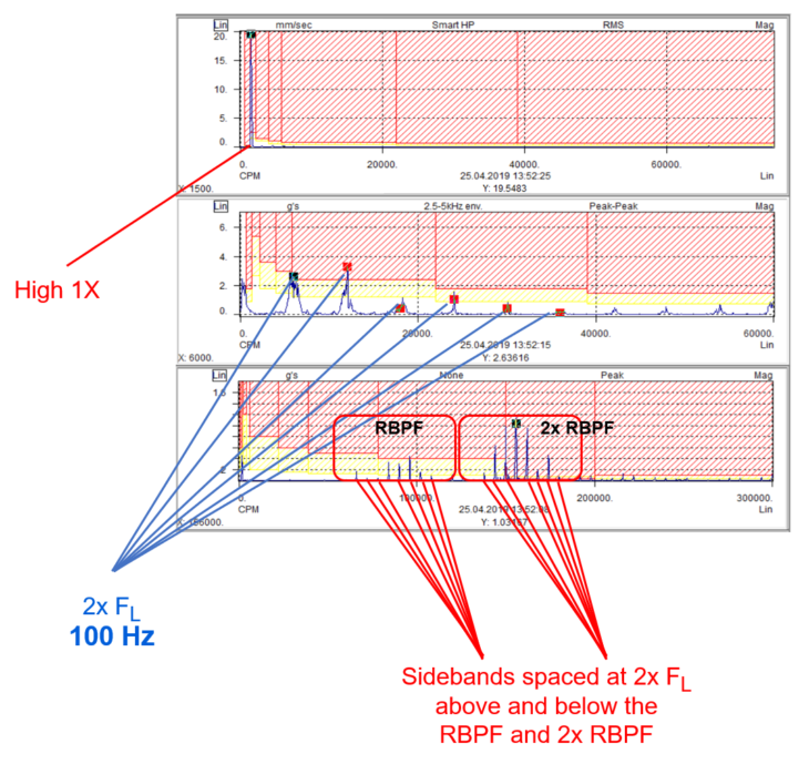
What could be observed in this case, excluding high 1X (19,548 mm/s) it is clear twice the line frequency with harmonics and some peaks at high frequency.
While looking deeper into high frequency the most dominant peak of 156 000 cpm could be seen accompanied by sidebands spaced above and below that frequency. These sidebands are spaced at ± 100 Hz or 6000 cpm.
There is also one more group of high frequency peaks where the center peak accompanied by sidebands spaced at ± 100 Hz or 6000 cpm is 78 000 cpm.
If we divide 156 000 cpm by 1500 cpm (1X) we have 104.
Then 78 000 cpm is exactly half of 156 000 cpm so if we divide 78 000 cpm by 1500 cpm we have 52.
Coming back to some theory of Part 1, the rotor problems are indicated by sidebands at twice the line frequency (2x FL) around the rotor bar pass frequency (RBPF) and / or its harmonics. Frequently, it will cause high levels at 2x RBPF with only a small amplitude at 1x RBPF.
Let’s look deeper:
1x RBPF – 78 000 cpm
2x FL around 1x RBPF – 66 000 cpm, 72 000 cpm, 84 000 cpm, 90 000 cpm, 96 000 cpm, 102 000 cpm, etc.
2x RBPF – 156 000 cpm
2x FL around 2x RBPF – 138 000 cpm, 144 000 cpm, 150 000 cpm, 162 000 cpm, 168 000 cpm, 174 000 cpm.
What written in theory confirms the case of rotor problem of high 2x RBPF with only small amplitude at 1x RBPF.
Having already confirmed the rotor problem, deeper analysis to be done to ensure it is only issue as the case looks more complex.
Coming back to the spectrum, the focus on high 1X and twice the line frequency to be done.
Twice the line frequency with harmonics can indicate stator eccentricity, shorted laminations or loose iron. Twice the line frequency with sidebands spaced at pole pass frequency (PPF) above and below the 2x FL can be also observed while rotor eccentricity.
1X may indicate unbalance, eccentricity or rotor bow. Important to know that the eccentric rotors produce a rotating variable air gap between the rotor and the stator which induces a pulsating source of vibration. As that, peak at twice the line frequency can be seen with sidebands spaced at pole pass frequency (PPF) above and below the 2x FL. The same pole pass frequency sidebands to be observed at running speed. What important, due to the eccentricity the 1X peak may be high.
Rotor bow can be present in similar way, except when rotor cools down the rotor may become straight again.
To dispel all the doubts further analysis requires “zoom” spectrum to separate 2x FL and running speed harmonics.
Let’s then zoom.
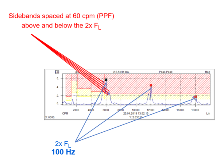
What could be observed in the spectra it is clear twice the line frequency with harmonics accompanied by sidebands. Sidebands as checked are spaced at ± 60 cpm (PPF).
Due to very high amplitude of 1X (19,548 mm/s) even when zoom, sidebands were not very clear, however pole pass frequency appears itself at low frequency.
Higher resolution measurements to be recommended if we have any doubts (at least 3200 lines of resolution; if available 6400 lines to be recommended) what could be also the case here, however even with currently used resolution PPF were clear enough, especially used only to confirm already detected rotor problem.
Interesting in this case was also to perform IR test and analyze thermal image. As could be seen the hot spot of 95°C is present. What important the high temperature is definitely not related to any bearing..
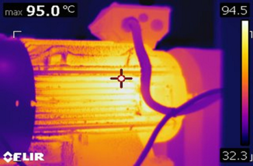
Having all collected facts, what could be expected as a potential problem is definitely rotor issue which could result also in eccentric rotor or rotor bow.
To confirm the analysis the corrective work was scheduled.
When motor was opened few things were noticed.
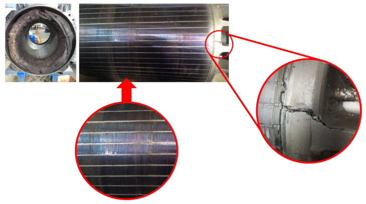
First of all the color of rotor bars. Look for blue, silver, gold and purple discoloration. These are the main symptoms of overheating. This kind of damage observed here is the result of dramatic temperature development in the motor. Hot spot of 95°C detected by IR was the temperature that was there continuously. To get the effect of discoloration as observed the temperatures in range of 200-300°C or more (looking tempering color of steel as a comparison) to be present. This, as confirmed could occur when once per time power supply failure and the machine full of product driven by analyzed motor to be started up.
The effect of this kind of overheating and discoloration could affect the loss of rotor bars hardness reducing rotor capacity to run optimally. In extreme cases the rotor could get deformed what could be the reason of eccentric rotor or rotor bow.
One more important thing observed is the crack on rotor construction. This kind of crack can be first step for further problems broken rotor bars including.
Summarizing the Part 2, both observations while motor repaired confirmed the analysis of rotor problems.
We have to remember, however to pinpoint specific electrical problems is not always that easy or even possible using vibration itself, so if any doubts other electrical and physical tests like MCE to be required.
Nevertheless, if vibration itself will give enough answer the steps presented in the article (Part 1 and Part 2) could be used as a step-by-step guide.


Hello
Could You help me?. I have a problem with a motor.
I Guess …. What… Is similar about it
.
Hello David,
sure, I can help you.
What doubts do you have?
Did you try to calculate frequencies as presented in my article?
What is your first feeling?
If you have any spectra please share so we can look together.
Thank you for the article Pawel
The analysis is a good case study. Always good to see the opened machine to confirm the analysis
I wonder if it is not a more efficient route to start with MCA after detecting the high motor temperature using Infrared
Hello Ian,
I aboulutelly agree with you.
As highlighted in part 1 of the article, to pinpoint specific electrical problems is not always possible using vibration itself. Other electrical and physical tests like MCE may be required.
Really vibration is the one of first choices following the P-F curve, taking also into account the wide range of problems to be detected by this CBM method. IR appeared later like a double check.
If nothing detected by vibration or not clear enough for sure to be confirmed by MCE. Luckly in this case vibration itself was enough.
Hello Sir, I have existing problem. Air compressor motor was running at 1800 CPM has a high vertical vibration at 4650 CPM which is at 2.6 order. The electrical line frequency was 60Hz (Philippines) or 3600 CPM. Can you give me an idea if what is the possible source of high vibration. Thank you