Best Practices for Electrical Resistance Heat Trace Systems in Process Plants
DESIGN, OPERATION, AND MAINTENANCE
AN EDUCATIONAL BLOG
By Mark Thomas, Reliability Professional, Allied Reliability
What is Heat Trace?
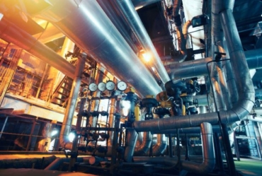
Heat trace refers to a method of controlled temperature employed in various industrial and commercial settings. It involves the use of an electrical heating element or cable to maintain a reliable, accurate temperature of process fluids or substances that are stored in pipes, tanks, or vessels. These days, you will find heat trace systems in almost all process plants where consistent temperature is critical to the manufactured product.
Types of heat trace
There are two types of heat trace systems: electrical resistance and steam. Steam heat trace is typically a standalone piping unit and will not be addressed in this blog article. Our focus will be on electrical resistance heat trace systems, which are usually installed underneath pipe insulation. Since these heat trace components are not visible during inspections, they require more specialized maintenance.
Note: The only physical evidence of a heat trace system during an equipment walkdown may be the terminal, i.e. termination box, where the power connection is made. This will usually have an indicator that lights up when the design voltage range is present.
Challenges of heat tracing
Detecting damage to a heat trace system under the surface is virtually impossible because of the surrounding insulation. And the insulation itself can become compromised, as it wears out over time from workers stepping on it, or changing weather and environmental conditions causing it to contract/expand. In either case, the heat trace system is subjected to moisture, rendering it totally worthless; without dry insulation, the heat trace simply cannot produce enough heat to be effective. It is false to think that the heat trace will keep the insulation moisture-free—it will not, especially if there is a break in the outer vapor barrier.
Note: In many plants, Allied Reliability consultants find “short-cut” crossings that eventually expose and damage the insulation and heat trace elements. This can be easily avoided by building a small footbridge to prevent vapor barrier damage.
Heat Trace Mechanism
The purpose of an electrical heat trace assembly is to produce a specific amount of heat at a specific current flow. It is often made up of two conductors in a flat, molded casing with a resistive substrate. It is connected on one end to a voltage source, 277V or 110V. At the other end is a terminal resistance between the two leads. The length of a trace is designed to provide the correct amount of resistance to the circuit. Terminal resistance is used to top off the resistance on shorter runs. Extra cable length is looped, without crossing over itself, to allow for slack where valves or other appurtenances may need to be removed or maintained.
System components
A complete electric heat trace system typically includes the following components:
- Attachment tape, for use on 12” intervals or required by local code or specification
- Cable end terminations, field junction boxes
- Electric heat trace cable (self-regulating, series resistance, parallel constant, or power-limiting)
- Thermostat control
- Thermal insulation and vapor barrier
- Transformer
- Process piping
- Control panels
- Asset number tag
System installation
Keep the following in mind to ensure successful installation of your heat trace system:
- The exact amount of terminal resistance needed is determined by the length of the heat trace cable.
- Splices and connections are troublesome because they add an unknown amount of resistance to the circuit.
- Cable splices are also more prone to failure. The splice failure can become loose at the splice due to a bad electrical fitting or if not installed correctly.
- The cable laid along the pipe or vessel, or spiral wrapped, may be a single or double longitudinal run.
- The pipe is then overwrapped with insulation, to direct the generated heat inward to the pipe contents.
- The heat trace is almost always covered by thermal insulation and a vapor barrier. This helps protect the insulation from moisture intrusion and physical damage, while also ensuring the proper functioning of the heat trace system.
- The vapor barrier should have a visible “Electric Heat Tracing” label, as required by code or specification.
Spares, Pumps, and Valves
Some companies routinely install a double run whenever replacing heat trace systems. The extra run is used as an ‘in-place’ spare. If a spare is installed, only one run is connected at a time, and the switch to the spare must be recorded in your asset history, so you can anticipate and prepare for the next failure.
- For a longitudinal run-on small diameter pipe, the two cables are simply run on opposite sides of the pipe.
- For a spiral run, a ‘barber pole’ wrap is used to ensure there are no crossovers.
Note: In-place spares must be electrically interlocked with the primary run to prevent self-induced damage; and careful records kept of the spare usage to facilitate timely, scheduled replacement of the abandoned circuit.
Pumps and valves can freeze; until recently, they were freely wrapped, leaving sufficient slack heat trace cable to allow for replacement or potential maintenance, without removing the entire heat trace run back to that point. This required the removal of insulation and was very time-consuming, disruptive, and very often did not get re-installed correctly. Newer systems have been designed that incorporate heat trace into the insulation, with formed ‘boots’ for valves and pumps. Each boot is connected to the heat trace via cable plugs, whose resistance is then calculated into the total run resistance. This allows for ease of valve or pump maintenance, with minimal disruption/downtime.
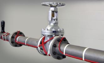
Heat trace protection applied to a valve, with vapor barrier removed.
Source: Applied Products Thermal Products Group
Life Expectancy and Failures
These values vary greatly, depending on design, environment, and usage. Common failures include physical compromises (damage due to outside forces), internal substrate breakdown (from overheating), and failure to replace components correctly after maintenance to the underlying structure. In some cases, failure of the supply circuit or harsh environmental conditions is indicated.
Maintenance & testing
Processes are often disrupted if the heat trace fails; therefore, heat trace operating conditions must be continuously monitored. This requires plant technician rounds, detailed history/recordkeeping, and a budget allocated for repairs. Seasonal testing is also highly recommended to proactively verify operational readiness.
Since heat trace systems are a maintainable asset, they must be tested, just like any other process control instrument. Be sure to include it in your Master Equipment List (MEL), even though it is not a Functional Location, per se. They are usually treated as assets within a location and monitored/maintained on a route basis.
Several predictive/preventive (PdM/PM) maintenance techniques can be used for monitoring heat trace condition and performance:
- Monitor the temperature and flow rate of the process fluid.
- Monitor the load current of any process-fluid-affected pumps set to alarm if a setpoint is exceeded.
- Periodically check the current level of the heat trace run.
- At a minimum, test the run seasonally via a resistance meter,* check for continuity, and record any issues.
*While some may argue that voltage and Ohm checks are sufficient, a Megger test is the most reliable method to verify the condition of electrical insulation and its resistance to a ground source. The best Megger reading is 2000 megohms on a 1000 VDC meter setting. Consider replacing a heat trace run if it registers between 2000 and “infinite.”
- Conduct seasonal operator rounds to inspect each heat trace run for visible damage or interruptions and check the indicator lights.
- Is the bulb working or has it burned out? The newer indicators now have LEDs attached to them and are less likely to burn out, but they also can have failures and need to be checked.
- The use of lighted end seals or end-of-circuit lights. Since most heat trace systems are not monitored remotely, indicator lights at the end of a run have become common. Note: While some technicians feel that the light will indicate if a circuit is working or not, it only really tells you there is voltage at the end of a run. It does not check for resistance or heat; it has no way of measuring the current or resistance.
- Don’t wait until winter to check your electric heat tracing system, it is too late by then.
- Be sure your maintenance procedures and standards include the correct removal and replacement of heat trace components.
- Stock critical spare components and cables. If your system still fails after all your checks, stocking spares will allow for timely repairs or replacements.
Cost Savings
The current economic shortages of process supplies has inflated the cost of operations. Heat trace systems contribute to an important cost savings for businesses by minimizing downtime; preventing pipe, tank, and pump failure; and reducing energy usage.
 The early investment in installing and maintaining these systems is offset by the continuing benefits of enhanced productivity, reduced repairs, and improved efficiency. With the capacity to moderate intense temperatures, heat trace systems protect process stability. They also prevent the formation of icing or solidification of liquids in pipes, pumps, valves, and tanks—thus reducing the risk of failures or disruptions in process flow. This guarantees uninterrupted production and increases uptime.
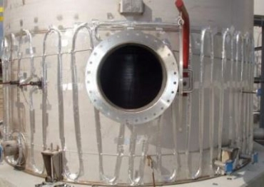
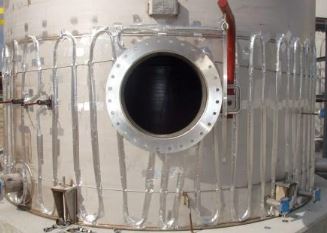
Heat trace protection applied to a tank, with vapor barrier removed.
Source: ICS Electrical Services
Summary
In addition to providing a detailed explanation of heat tracing in general, this educational blog has recommended several heat trace maintenance guidelines to make sure the preventive maintenance of your process equipment best meets the needs of your company or organization. Precise temperature control is critical to certain industrial processes in which the end product integrity depends on it. Therefore, investing in a heat trace system and maintaining it properly enables high-quality standards to be met, leading to safety and customer satisfaction. Outsourcing the monitoring and maintenance tasks can be a cost-effective solution at a time when resources are scarce and tight.
Wherever you are on your reliability journey. Our Reliability Professionals have the experience and expertise to assist with your heat trace system—from inspection to monitoring, to condition-based maintenance (CBM)—as well as creating an asset hierarchy list of heat trace components in your computerized maintenance management system (CMMS). If you would like further guidance or support in improving or establishing better reliability pertaining to this technology, please contact one of our many professionals.
About the Author
Mark Thomas

In his current role with Allied Reliability, Mark is a reliability consultant responsible for working closely with clients to design, train, and implement preventive maintenance (PM) and reliability continuous improvement programs. Prior to his role with Allied Reliability, Mark held several roles with Emerson Automation Solutions.
Mark holds the CMRT and Lean Six Sigma Yellow Belt Certifications. He is a seasoned field and plant service technician with a demonstrated history of working in the mechanical or industrial engineering industry. He is skilled in petroleum, technical support, inspection, databases, and plant maintenance. Mark is a strong support professional with an Associate of Science (AS) focused on Industrial Electronics Technology/Technician from Missouri State Fair Community College.
Connect with Mark on LinkedIn.


A great article. Couldn’t stop reading it. This is what my plant needs. They are always chasing problems with the heat trace. Thanks Mark!
Terrific explanation of heat trace systems and the various applications. Appreciate the reminder of the cost saving measures, as well as, the pictures.
I continually maintain these types of systems in my plant. After reading this article I will find many ways to improve this troublesome process.
Hi..Good to your article…I too have pipeline which is burried, Coated,Heat traced and insulted with CP ..Yet we have corrosion..Can you suggest best practices to prevent 8n future..