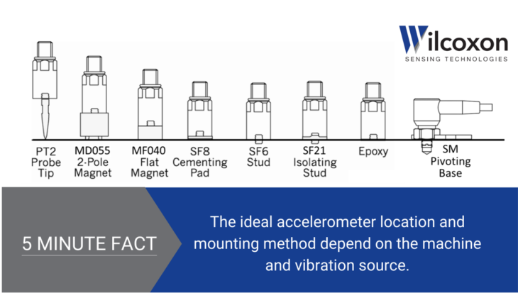
Vibration practitioners must evaluate and determine the mounting location and method of their vibration sensor for each machine and vibration source to be monitored.
For all installations:
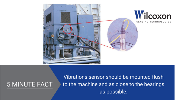
The piezoelectric vibration sensor must be as close as possible to the machine’s surface.
The sensor should be mounted in a location as close to the bearings as possible.
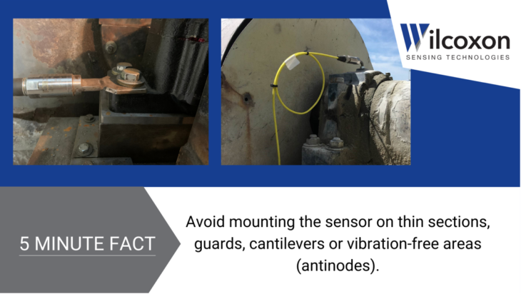
Avoid mounting the sensor on thin sections, guards, cantilevers or vibration-free areas (antinodes), or areas with extreme temperature variations.
For permanent installations:
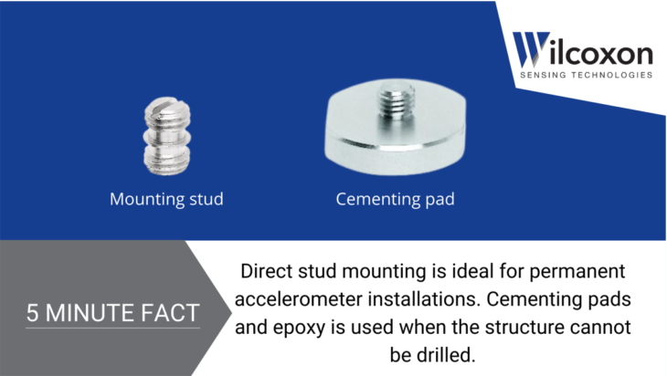
Direct stud mounting or epoxy and cementing pads are most commonly used.
IDEAL: Threaded stud mounting, via a tapped hole drilled directly into the structure, provides an electrical and mechanical connection between the sensor and machine.
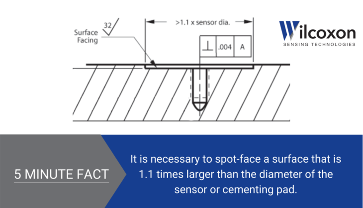
Flush mounting requires a flat spot-faced surface that is 1.1 times larger than the diameter of the sensor housing.
Burrs between the sensor and the machine must be eliminated.
The centerline of the tapped hole must be perpendicular within 1° to the mounting surface to ensure no gaps are present between the base of the sensor and the structure.
The tapped hole and spot face can be machined in one stop with proper tooling.
GOOD: When the structure to be monitored cannot be drilled, cementing pads provide rigidity approaching that of stud mounts when used properly. The flat side is bonded to the machine with an appropriate adhesive. The opposite side contains a stud or tapped hole for mounting the sensor.
A spot-faced surface that is 1.1 times larger than the diameter of the cementing pad is required.
Allowing the machine tool to groove and abrade the surface prepares it for adhesive bonding.
ACCEPTABLE: Epoxy mounting provides a secure attachment without extensive machining but can reduce the operational frequency range since the adhesive acts like a shock absorber, known as damping.
For route-based data collection:
IDEAL: Permanently installed cementing pads are often used to create a quick connection point on routes. They provide the requisite rigidity and ensure consistent measurement locations for walk-around applications.
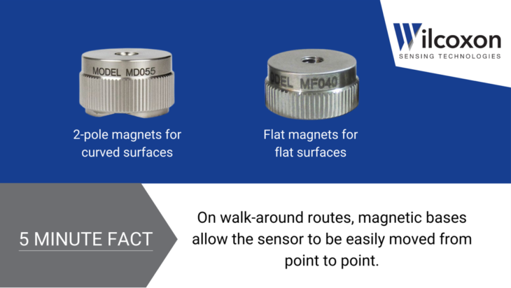
GOOD: Magnetic bases allow the sensor to be easily moved from point to point.
2-pole magnets provide the best connection on curved surfaces.
Flat magnets are ideal for flat surfaces. Coupling fluids, such as silicone grease or oil, greatly improve measurements with flat bottom magnets and should be used whenever possible.
For accurate trending, mark measurement locations to ensure readings are taken at the same place every time. Magnetic mounting targets are also available for certainty and repeatability.
Magnetic bases produce a significantly different response at higher frequencies compared to stud and cementing pad measurements. Caution must be exercised when viewing data higher than 1,000 Hz.
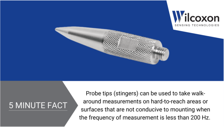
ACCEPTABLE: When the frequency of measurement is less than 200 Hz, probe tips (stingers) can be used to take readings on hard-to-reach areas or surfaces that are not conducive to mounting.
For high-frequency vibrations:
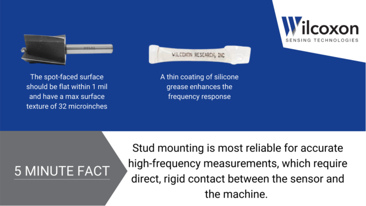
Accurate high-frequency signals are dependent on direct, rigid contact between the sensor and the machine. Stud mounting is the most reliable mounting option because it can achieve the sensor’s maximum frequency range. A thin coating of silicone grease can increase mounting stiffness and enhance frequency response.
For measurements above 1,000Hz (60,000 cpm), the spot-faced surface should be flat within 1 mil and have a surface texture no greater than 32 microinches.
Avoid small debris between sensor and surface, this can dramatically reduce the upper frequency response limit.
Magnetic bases and probe tips are not recommended because of the lower resonant frequency of the coupled system.
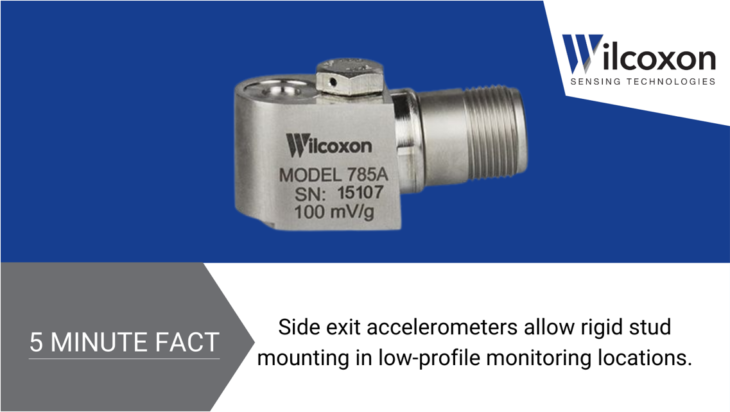
For low-profile installations:
Side-exit accelerometers provide rigid stud mounting in monitoring locations with low overhead clearance.
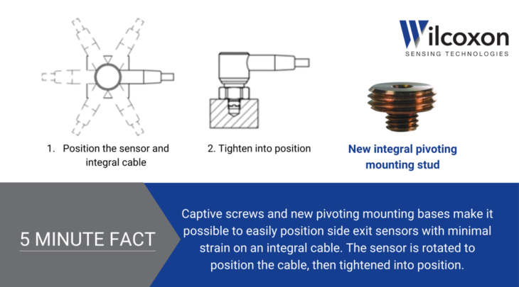
New pivoting mounting bases make it possible to easily position the sensor and connector with minimal strain on the integral cable. Installation begins with threading the sensor’s hex nut onto the mounting stud, which is already installed on the machine. Then, the sensor is rotated to position the integral cable. When the desired orientation is achieved, the hex nut can be tightened.
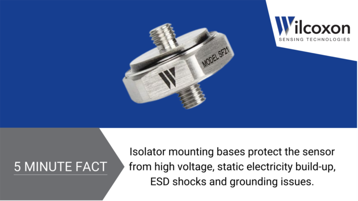
For electrical isolation:
Isolator mounting bases protect against high voltage, static electricity build-up, ESD shocks and grounding issues such as poor ground bonding, ground loops or different ground potentials.
They are mounted to the machine surface via tapped hole and can be improved with a thin, rigid layer of adhesive.
To avoid unintended conduction, ensure all contaminants are removed from isolation material.
Peter EitnierSenior Applications Engineer, Wilcoxon Sensing Technologies
Peter Eitnier is a Senior Applications Engineer at Wilcoxon Sensing Technologies in Frederick, Maryland. He holds an ISO CAT II Certification as a vibration analyst and a degree in Mechanical Engineering from the University of Maryland. Since joining Wilcoxon in 2012, he has specialized in providing technical expertise to customers in a variety of applications.
By using this site you agree to our use of cookies. You are free to manage this via your browser setting at any time. To learn more about how we use the cookies please see our cookies policy.