Imbalance, misalignment, bearing faults, gear mesh failure—many of the most common failure modes of standard equipment can be detected using vibration analysis. In simple terms, vibration monitoring works because machine faults have specific vibration signatures. While vibration frequencies can help determine the mode of failure, the amplitude of the vibration can help determine the severity of the problem.
But with all of the options available in the preventative maintenance market today, how do you determine which vibration monitoring devices are the best fit for your facility?
The following overview provides a look at the capabilities and limitations of common options, including vibration switches, vibration transmitters, and wireless vibration systems.
Vibration Switches
Vibration switches are relatively simple instruments used to protect rotating machinery against failure due to excessive vibration. Vibration switches continuously monitor vibration on a machine and provide an alert and/or shutdown of the machine, depending on the type of vibration switch and its configuration, when vibration levels become too high.
There are two basic types of vibration switches: mechanical and electronic. However, with today’s microprocessor technology, electronic vibration switches can be further subdivided into two types, traditional electronic and programmable electronic vibration switches.
Mechanical vibration switches (or “earthquake switches”) provide basic protection at a low cost for less critical machinery. These switches are easy to install, do not require power to operate, and are the most basic type of vibration switch protection available.
Mechanical switches utilize the resistive force and travel of a spring as a measure of vibration amplitude. When the travel of a spring exceeds the predetermined threshold, the switch is actuated and latched by magnetic attraction. The threshold value is adjustable by changing the proximity of the magnet to the spring and hence the spring travel required for actuation. Switch reset is accomplished manually by disengaging the magnet from the spring.
The major disadvantages to this design is that there is no accuracy in setting a trip level, it has different sensitivities in various directions, its response is not very repeatable, and it will not trip due to a pure unbalance condition without secondary effects. Furthermore, environmental sealing is often lacking due to the mechanical adjustment screw. Corrosion due to poor sealing can change switch sensitivity, making it less sensitive over time to shock and vibration.
Electronic vibration switches have several advantages over mechanical units. They have no moving parts, are more reliable and have a much higher degree of accuracy.
Electronic switches use a built-in precision accelerometer to monitor vibration levels, rather than a spring-latch mechanism. An electronic switch consists of an accelerometer, circuit board and one or more electromechanical or solid state relays for alarm and shutdown protection. The internal circuitry monitors the sensor’s vibration level and compares it to a preset threshold or alarm value. When the vibration level exceeds this threshold, the relay is then activated.
Mechanical vibration switches are, by default, latching, meaning once they trip they stay tripped until reset by someone. Electronic switches can operate this way as well, but can also be set to non-latching. This means that after a relay is tripped, it will automatically reset itself when the vibration level drops below the alarm level.
In an electronic vibration switch, the set point is either fixed or adjusted electronically through the use of programming software. Programmable accelerometers provide the ability of a user to set a specific numerical value (in velocity) for the threshold, putting an end to the era of unreliable set points.
An additional convenience of electronic vibration switches is the option of time delays, the most common being startup and alarm delays. A startup delay allows for an amount of time where the vibration level is ignored until the machine achieves steady state operation. With an alarm delay, vibration must exceed the threshold for a specified delay time period in order for the switch to trip. This avoids a shut-down for random transient events, such as bumping into the machine.
Vibration Transmitters
Another vibration monitoring method makes use of existing plant monitoring instrumentation. This method combines the capabilities of low-cost piezoelectric vibration sensors and 4-20mA vibration transmitters to directly communicate with PLC, PI, SCADA, or DCS systems. These systems can test continuously, providing a performance record over time to aid in fault diagnosis.
See Figure 1 for an example setup of such a system.
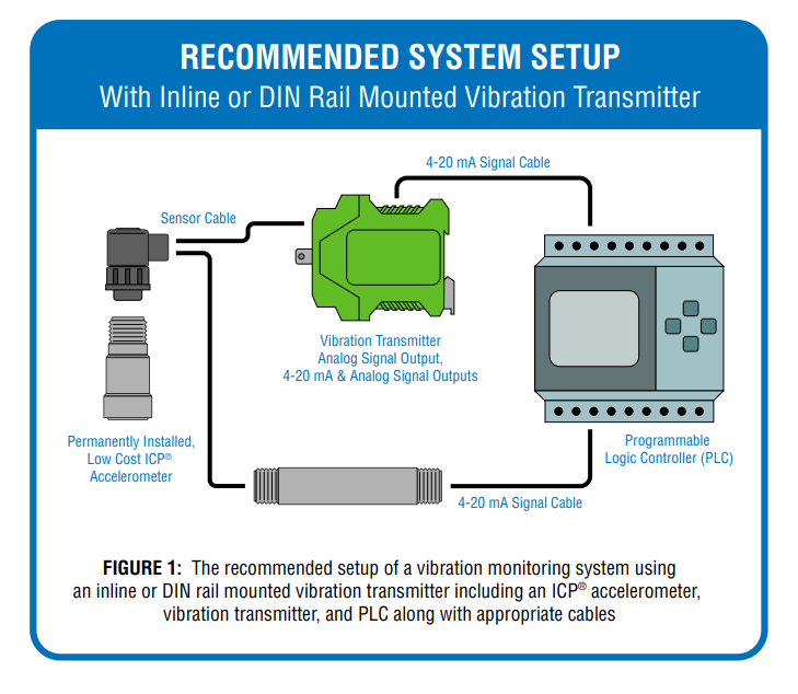
In this system, when vibration levels become excessive, the PLC will alert the predictive maintenance team of the need for closer investigation to pinpoint the exact failure mode. That analysis is further facilitated by a raw vibration signal also available through the vibration transmitter that can be analyzed with portable diagnostic equipment.
This approach is cost effective since plant monitoring devices such as PLCs are widely used in many factories. Vibration channels can be added at a fraction of the cost of adding separate redundant vibration monitoring equipment. Other costs, such as installation and training, also are reduced since the monitoring instrumentation already is installed and trained personnel are in place.
Wireless Vibration Monitoring
Wireless vibration sensors and systems are a new breed of monitoring that is growing in popularity. Unlike vibration transmitters that monitor continuously, these systems typically collect data and check it against alarm levels a few times a day, providing data to existing monitoring devices. They have the advantage over vibration transmitters in that they don’t require expensive cable runs. Wireless technology also allows measurements to be taken on machines in dangerous, remote and hard-to-reach locations, such as high temperature areas or in extreme heights.
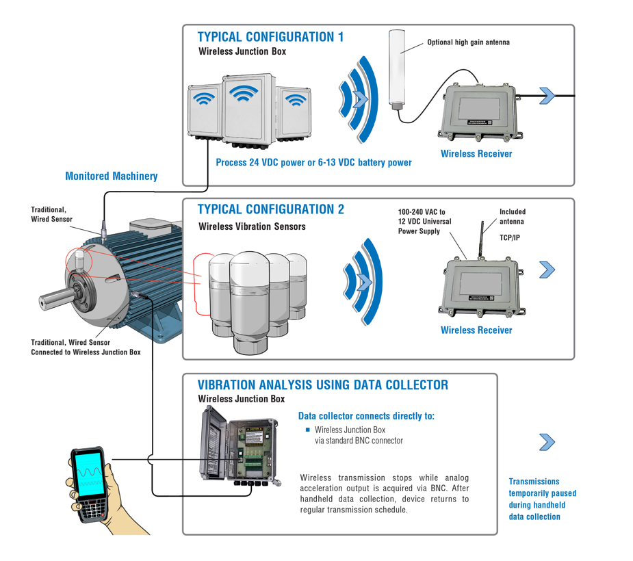
Configurations vary among wireless systems, but a typical configuration consists of a wireless sensor that transmits data to a receiver, which is then sent via Ethernet to the PLC. Traditional sensors may be used in place of wireless sensors but require wiring to a junction box to convert the signal to the receiver. For fault diagnosis, this method also allows full data collection with a portable data collector at the box.
A possible disadvantage of wireless sensors is that they run on battery power—and the more frequently you collect data, the shorter the battery life. For this reason, systems typically do not run continuously but are rather set to take measurements at set intervals. This schedule works best for long failure mode equipment, that is, on machinery that can run safely for a time after the initial occurrence of excessive vibration.
A final consideration is that, while these sensors can often go in places people should not, the signal still has to be able to travel. Signals are especially limited in areas with high electric fields, so it’s important to check range when considering wireless.
Key Considerations
When implementing any vibration monitoring program, it’s important to know your machinery, its likely faults, and how those faults will be expressed in terms of vibration irregularities. With the above capabilities and limitations in mind, consider: Can the unit be shut down immediately if vibration goes beyond a specified threshold, or do you need to be alerted as that threshold is approaching? Do you need continuous monitoring to provide vibration trends over time, or will periodic monitoring serve the purpose?
Though sensor systems are becoming more sophisticated and convenient in their design, they are still not designed to replace human analysis, and will not diagnose or repair a fault. The best monitoring device for any preventative maintenance program is the one most likely to prevent damage before it occurs.
Martin, Bob. How to Use Condition Based Analysis to Solve Your Equipment Failures
https://www.cbmconnect.com/how-to-use-condition-based-analysis-to-solve-your-equipment-failures/
Corelli, David. Understanding Vibration Switches
https://www.pcb.com/contentstore/mktgcontent/whitepapers/WPL_55_UnderstandingVibrationSwitches.pdf
Saller, Eric. Continuous Condition Monitoring With Vibration Transmitters and Plant PLCs
https://www.pcb.com/contentstore/MktgContent/WhitePapers/WPL_47_ContinuousMonitoring.pdf